In the Laboratory of Laser and High Speed Machining (P8) research and implementation tasks are carried out in the field of machining difficult-to-cut materials used in aviation technology. The laboratory established close cooperation with WSK "PZL Rzeszów" S.A, under which the machinability of a modern titanium alloy on a matrix of the TiAl (γ) intermetallic phase was tested. The result of the cooperation was the development of the machining technology and the production of a demonstrator in the form of a low pressure turbine blade made of TiAl (γ) alloy, and the development and implementation of machining technology for bodies made of two-phase titanium alloys used in aircraft structures. The HSM laboratory, as a partner of WSK "PZL Rzeszów" S.A., participated in the implementation of tasks under three EU projects: NEWAC, VITAL and LEMCOTEC, which will result in the development of a new ecological aircraft engine with reduced CO2 and NOx emissions and a lower noise level. A technology for machining samples for strength and fatigue tests, accredited by NADCAP, was also developed. The test equipment, which is also the equipment of the HSM laboratory, enables the study of the cutting process in terms of measuring the components of the cutting force, temperature in the cutting zone, surface roughness and vibrations in the processes of turning, milling and drilling.
The basic equipment of the HSM lab includes:
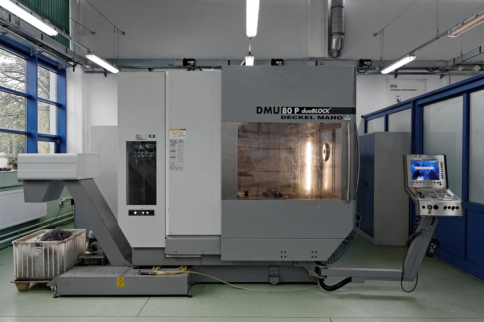
- Deckel Maho DMU 80P machining center - 5-axis HSM machining center, working space: 800/800/800 mm, rotary axes: B (head) and C (table), spindle: n = 18,000 rpm, P = 28 kW, M = 121 Nm, tool magazine: 40pcs, HSK-A63, control system: Sinumerik 840D Powerline, measurement of the working space: workpiece and tool, cooling: through the spindle, 2 pressure levels 4/8 MPa, MQL system, system oil mist removal.
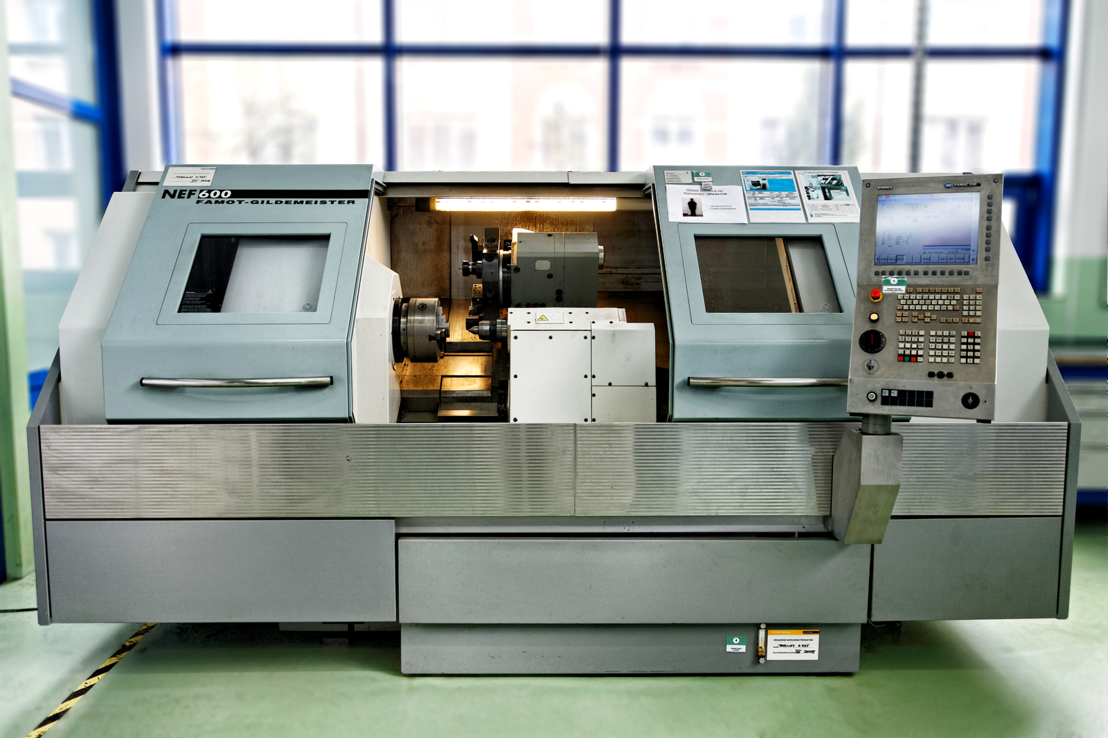
- CNC lathe NEF 600 - working space: max turning diameter 600 mm, longitudinal travel 1250 mm, main drive P = 18 kW, n = 3000 rpm, M = 615 Nm, number of tool stations: 8, control system: GE Fanuc 210i, tool holder: VDI 40, Sandvik tool kit.
- A device for presetting and measuring tools Mikroset ECO210 - setting and measuring tools outside the machine's space, manual spindle guarantees high accuracy of measurement. Balancing machine for rotary tools Haimer Td1002 - automatic tool clamping, rotational speed range: 300-1100 rpm, power: 0.4 kW, max tool length: 360 mm, max tool diameter: 340 mm, max tool weight: 30 kg.
- Kistler 9123CXX11 piezoelectric rotary force gauge - measurement of cutting force components in three axes, operation at maximum rotational speed: 10,000 rpm, maximum tool diameter: 18 mm.
- Stationary piezoelectric force gauge Kistler 9257BA - measurement of cutting force components in three axes, max force: 5 kN, CutPRO software, measurement of cutting force, visualization, analysis and archiving of measurements, analysis of machine tool stiffness and simulation of the cutting process.
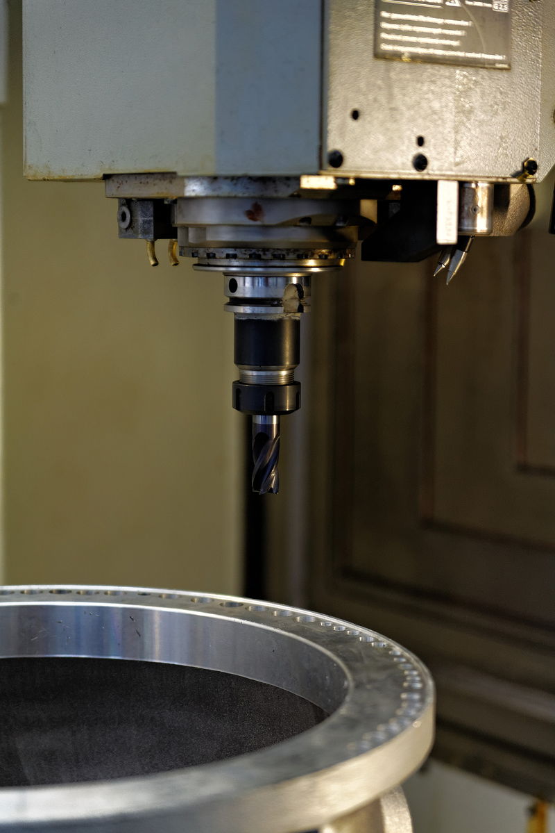
The P8 laboratory also conducts the processes of deposition and surfacing of powders of metallic materials with the use of a laser beam, cutting holes of small diameter in both metallic and ceramic materials. Processes for the production of protective layers with good corrosion resistance, including high-temperature corrosion, abrasive wear and erosion by laser surfacing, using metal alloy powders as an additional material are being developed.
The equipment of the P8 lab is as follows:
- TRUMPF Nd: YAG - TruPulse 203 pulsed laser - processes of cutting small diameter holes (0.3 - 0.6 mm) in rotating (blades) and stationary (directing devices) parts of hot aircraft engines with coated thermal barriers (Fig. 1), also cutting and pulse welding. The wavelength of the laser radiation λ = 1064 nm, the maximum pulse power 6 kW and its energy 55 J. The time of the radiation pulse is variable in the range from 0.3 to 50 ms, while the frequency of the pulses from 0.1 to 833 Hz.
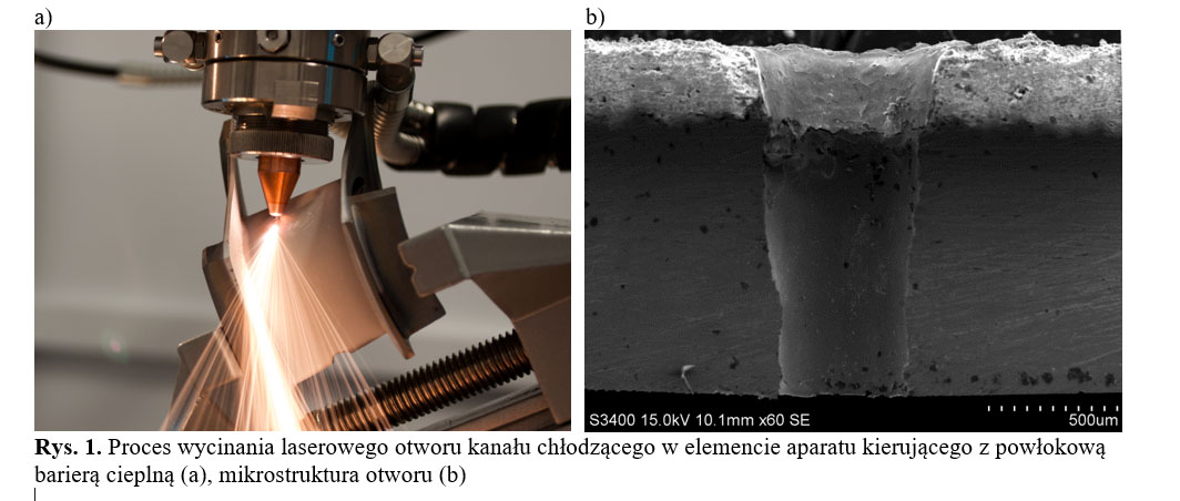
Fig. 1. Laser cutting process of a cooling channel hole in a vanes with thermal barrier coating (a), hole microstructure (b)
- TRUMPF Yb: YAG - TruDisk 1000 disc laser - laser cutting, welding and surfacing processes. Wavelength of laser radiation λ = 1030 nm, pulsed and continuous beam with a maximum power of 1 kW. The laser enables laser cutting of steel elements 10 mm thick, corrosion-resistant steel - 5 mm, aluminum and aluminum alloys - 3 mm and copper - 1 mm (Fig. 2). The processes of welding steel sheets up to 2 mm thick and made of corrosion-resistant steel up to 1.5 mm thick are carried out. As part of the research, laser surfacing processes are developed using powders of cobalt alloys, nickel superalloys, corrosion-resistant steel and alloys with a high carbide content - WC-Co.
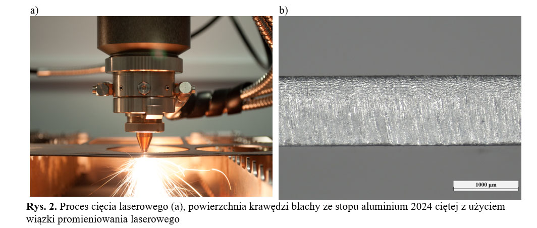 Fig 2. Laser cutting process (a), the surface of the edge of aluminium alloy 2024 sheet cut using a laser beam (b)
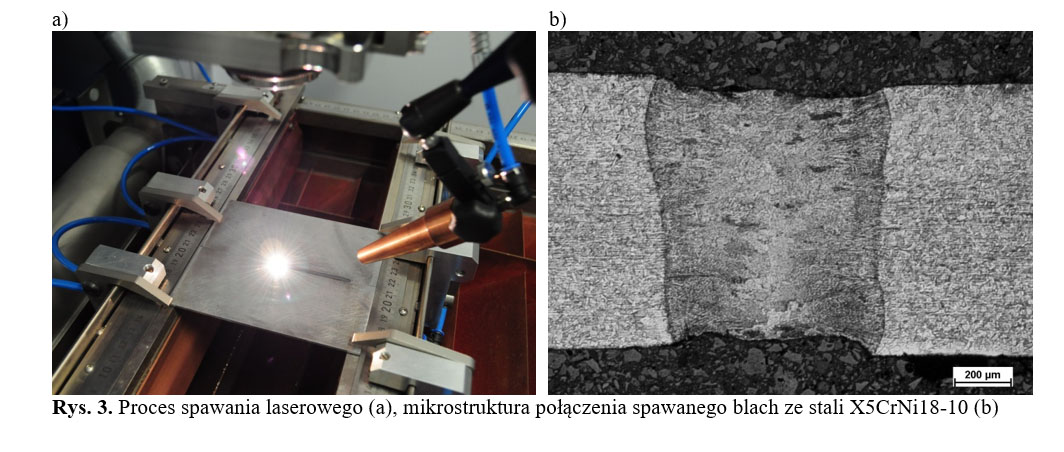 Fig. 3. Laser welding process (a), microstructure of welded joint of X5CrNi18-10 steel sheets (b)
- TRUMPF TruLaser Cell 3008 laser machine (fig. 4a) - processing in 5 axes at a speed of up to 30 m/min. Head displacement: in the X axis - 800 mm, Y - 500 mm, Z - 400 mm. It is equipped with a rotating axis and a tilting angle within the range of ± 90°. The processes of laser cutting and cutting holes of small diameter are carried out by means of a head with a focusing lens with a focal length of f = 150 mm equipped with replaceable nozzles with a hole diameter of: 0.5; 0.8; 1.0; 1.2 and 1.7 mm. Maximum pressure of working gases: N2 - 2.5 MPa, O2 - 1.0 MPa, Ar - 1.0 MPa and air - 0.8 MPa.
The welding and surfacing processes are carried out using a laser head with a focusing lens with a focal length f = 220 mm (Fig. 4b). The additive material in the form of powder is supplied through 3 holes located in the nozzle of the head. The machine is equipped with a GTV PF 2/1 powder feeder with a capacity of 1.5 dm3, enabling the use of spherical powders and particle diameters in the range of 30 - 120μm.
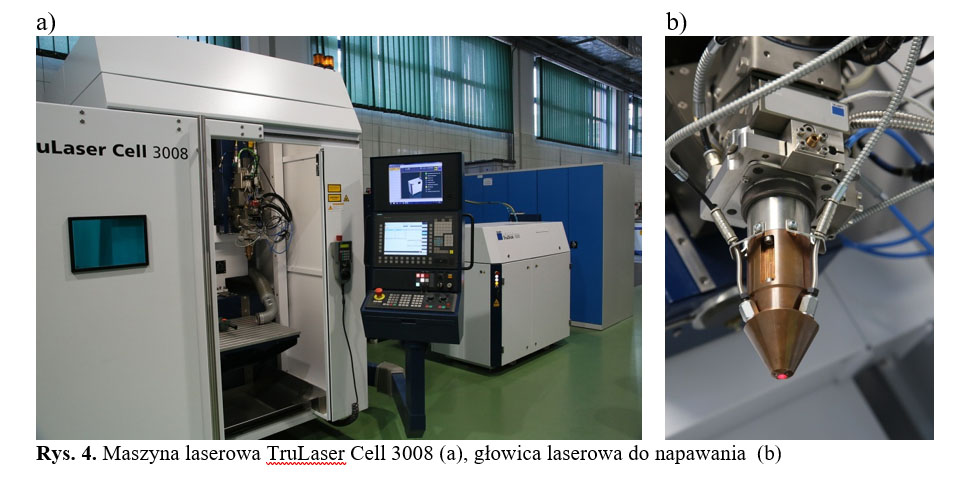
Fig. 4. TRUMPF TruLaser Cell 3008 laser machine (a), laser head (b)
- TRUMPF TruTops Cell v6.0 software - programming of 2D and 3D laser processing - cutting, welding and laser surfacing (Fig. 5). The software works with files created in the following programs: AutoCAD, Inventor and CATIA, as well as digital IGES and STL file formats.
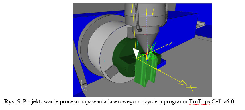
Fig. 5. Process design for laser deposition using TruTops Cell v6.0


